


Please Leave Us A Message
Privacy statement: Your privacy is very important to Us. Our company promises not to disclose your personal information to any external company with out your explicit permission.

 September 28, 2021
A band-pass filter is a device that allows waves of a specific frequency band to pass while shielding other frequency bands. For example, the RLC oscillator circuit is an analog bandpass filter.
A bandpass filter is a filter that can pass a frequency component in a certain frequency range but attenuate other ranges of frequency components to an extremely low level, as opposed to the concept of a bandstop filter. An example of an analog bandpass filter is a resistor-inductor-capacitor circuit (RLC circuit). These filters can also be generated using a low pass filter in combination with a high pass filter.
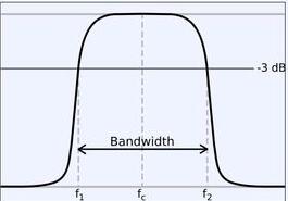
working principleAn ideal bandpass filter should have a completely flat passband that is not amplified or attenuated in the passband, and all frequencies outside the passband are completely attenuated. In addition, the transition outside the passband is minimal. The frequency range is complete.
In fact, there is no ideal bandpass filter. The filter is not able to completely attenuate all frequencies outside the desired frequency range, especially outside the desired passband, with a range that is attenuated but not isolated. This is commonly referred to as the roll-off phenomenon of the filter and is expressed in dB of the attenuation amplitude per decade. In general, the filter is designed to ensure that the roll-off range is as narrow as possible, so that the performance of the filter is closer to the design. However, as the roll-off range becomes smaller and smaller, the passband becomes flatter and begins to “ripple”. This phenomenon is especially noticeable at the edges of the passband, an effect known as the Gibbs phenomenon.
In addition to electronics and signal processing, an example of a bandpass filter application is in the field of atmospheric science. A very common example is the use of a bandpass filter to filter weather data over the last 3 to 10 days, so that the data Only the cyclone that is disturbed is retained in the domain.
Between the lower shear frequency f1 and the higher shear frequency f2 is the resonant frequency, where the gain of the filter is the largest, and the bandwidth of the filter is the difference between f2 and f1.
typical application
Many audio analyzers use this circuit as a bandpass filter to select the signals in different frequency bands, and use the LED to indicate the magnitude of the signal on the display. The center frequency of this active bandpass filter, the voltage gain at the center frequency fo Ao=B3/2B1, the quality factor, the 3dB bandwidth B=1/(п*R3*C) can also be determined according to the design Q, Fo, Ao value, to find the parameter values of each component of the band pass filter. R1 = Q / (2 пfoAoC), R2 = Q / ((2Q2-Ao) * 2 пfoC), R3 = 2Q / (2 пfoC). In the above formula, when fo=1KHz, C takes 0.01Uf. This circuit can also be used for general frequency selective amplification. Active bandpass filter circuit
This circuit can also be used with a single supply, simply biasing the positive input of the op amp to 1/2V+ and the lower end of resistor R2 to the positive input of the op amp.
Bandpass filter schematicBandpass Filter Schematic The value of R1 is determined in advance in this circuit. Its size is close to the internal resistance r1 of the signal source. The principle of parameter selection is R4=R3, C1 is approximately equal to C2, and Q is less than or equal to R1,500K"R"1K, 0.5uF 》C》200pF.
Bandpass filter schematic
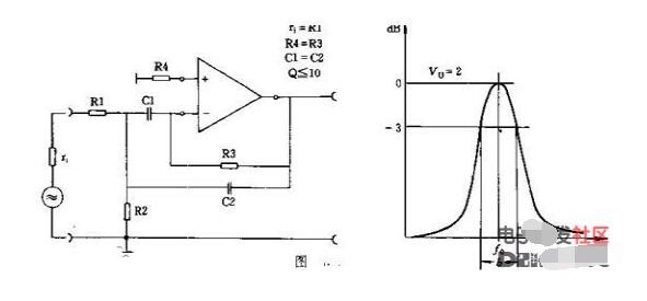
The value of R1 is determined in advance in the circuit, and its size is close to the internal resistance r1 of the signal source. The principle of parameter selection is R4=R3, C1 is approximately equal to C2, and Q is less than or equal to R1,500K"R"1K, 0.5uF"C"200pF.
The above is the Bandpass filter detailed _ bandpass filter working principle _ bandpass filter schematic we have listed for you. You can submit the following form to obtain more industry information we provide for you.
You can visit our website or contact us, and we will provide the latest consultation and solutions
Send Inquiry
Most Popular
lastest New
Related Products
Send Inquiry
Privacy statement: Your privacy is very important to Us. Our company promises not to disclose your personal information to any external company with out your explicit permission.
Fill in more information so that we can get in touch with you faster
Privacy statement: Your privacy is very important to Us. Our company promises not to disclose your personal information to any external company with out your explicit permission.